How Lattice Design Improves Strength-to-Weight Ratio in 3D Printing
If you've ever looked at a rocket bracket or a drone arm and wondered why it looks more like a honeycomb than a solid block, that's a 3D printed lattice structure at work. Instead of filling the part with solid material, engineers hollow out the inside and replace it with a repeating pattern of beams and nodes, basically the same trick nature already pulled off inside a bird's wing or a piece of bone. The part ends up using a fraction of the material and still holds up under the load it was built for.
None of this is new, honestly. Engineers have leaned on lattice patterns for over a century, and the Eiffel Tower is proof enough of that. What's changed is that additive manufacturing can finally produce these patterns at a resolution nothing else comes close to. The American Society of Mechanical Engineers credits additive manufacturing as the technology that made complex lattice patterns production-viable at a scale conventional manufacturing methods simply can't touch.
What Makes a Lattice Structure Different From a Solid Part
Strip it down to basics and a lattice structure is a repeating cell pattern, a network of nodes connected by beams, sitting where solid plastic or metal would normally be. The building blocks are called unit cells, and the unit cell size you choose, along with the cell type, decides how the finished part behaves under load.
Not every manufacturing method can even attempt this. Additive manufacturing builds a part one layer at a time, reaching into internal structure that no other manufacturing method can touch, though not every one of the 3D printing technologies out there handles it equally well. Traditional subtractive processes can't cut inside a closed volume without opening it up first, and injection molding fills a cavity completely, full stop. Even fused deposition modeling, the desktop-style process most people picture when they hear "3D printer," struggles here, since it needs internal supports that are nearly impossible to remove once the part is sealed. That's a big part of why complex lattices showed up in serious product design and aerospace parts long before they ever showed up in a hobbyist's PLA print.
Why Lattices Improve the Strength-to-Weight Ratio
Normally, removing material weakens a part. Less material means less to carry the load, that's just how it works. Lattices break that trade-off by putting material only where the load actually travels through the part, not everywhere it might.
This is where topology optimization software earns its keep. It analyzes where stress concentrates and strips material from the low-stress regions first, the areas that were never doing much mechanical work anyway. What's left gets filled with a lattice tuned to the load path, so instead of one thick wall carrying everything alone, the load spreads across hundreds or thousands of small members.
That deformation behavior is one of the more important design elements to get right. A well-built lattice absorbs energy through a gradual mechanical response instead of failing all at once. Some patterns show an elastic response and spring back; others show an inelastic response and stay crushed, which is the whole goal in a part built for impact or shock absorption, like a packaging insert or a protective housing. Engineers describe these mechanical properties as a modulus, measured in MPa, tuned by adjusting cell size and wall thickness without ever changing the base material. Push a lattice too far past its intended load and the walls buckle rather than crack cleanly, usually the safer way to fail in a real product.
Common Lattice Patterns
The curved shape in that gyroid row belongs to a family engineers call TPMS, short for triply periodic minimal surface, a technical way of saying it repeats in three directions with no sharp edges anywhere. That's why gyroids and similar continuous patterns don't need internal print supports and spread load evenly no matter which direction it comes from. Lattice material choice matters just as much as the pattern itself here. Parts with lattice interiors printed in a brittle resin behave nothing like the same 3D-printed parts made in a tough engineering nylon.
From CAD Model to Printed Lattice
You don't create a lattice by hand, cell by cell, past a certain complexity. This whole design phase leans on dedicated lattice-generation and topology optimization software tools rather than standard CAD, since checking thousands of repeating unit cells by hand isn't realistic. It's exactly the kind of work our design and application engineering team handles before a part ever reaches the print queue.
- Define the boundary. The outer shell usually stays solid where the part mates with other components or needs a finished surface.
- Run topology optimization. Simulation software flags where stress is high and where it isn't, the whole point of a robust design instead of a guess.
- Pick a lattice pattern and cell structure. Match it to the load direction, a crush-resistant pattern for one plane, a continuous pattern for even multi-directional load.
- Export and simulate. The lattice gets exported as an STL file and stress-tested digitally to confirm it holds under real loads before it ever reaches a build plate.
Density doesn't have to be uniform either. If 80% of the load sits on one side of a bracket, that section can be thickened while the rest stays lighter, so material lands exactly where the part needs it.
Printing Lattices in HP MJF: The Numbers That Matter
A design only works if it can be printed and cleaned in the real world, not just simulated on a screen. On HP's Multi Jet Fusion process, per the HP MJF Handbook, the recommended minimum gap for clearing unfused powder out of a lattice is 2.5mm, about 0.1 inch. Go tighter than that and the powder stays trapped inside the part permanently. General MJF tolerances for mating surfaces sit at a minimum gap of 0.4mm with ±0.2mm tolerance per part, and minimum wall thickness runs 0.3mm in the XY plane and 0.5mm in the Z direction. These are process-specific numbers, not a generic machining tolerance chart, and that's precisely where a lot of latticed designs go wrong. If you want the fuller picture on wall thickness, overhangs, and feature sizing beyond just lattices, our design for additive manufacturing guidelines cover that ground.
MJF is also a support-free process. The surrounding unfused powder bed physically holds every beam in place while it prints, so there's no support material to plan around or dig out afterward. Because the whole powder bed fuses together in a single pass, the resulting parts are isotropic, meaning strength doesn't vary much by direction the way it can with processes where layer adhesion is the limiting factor, which matters once your load path runs through a lattice from more than one angle.
Real Weight Savings: A Verified Example
Vague percentages don't help anyone design a part. HP's own case documentation shows an aluminum machined bracket weighing 355 grams redesigned with topology optimization and a lattice interior, printed on HP MJF, that came in at 23 grams. That's a 90% weight reduction on a real part, not a marketing estimate, along with a documented carbon footprint drop from roughly 19.7 kg CO2 equivalent to 0.97 kg CO2 equivalent for that specific part. It's a real example of a high strength-to-weight ratio in practice, and it's a big part of why product design teams reach for lattices when the goal is simply to make parts lighter without giving up structural integrity.
Where This Gets Used in the Real World
Aerospace: Aerospace 3D printing leans on lattice brackets and mounts because every gram removed from a launch payload saves real fuel cost down the line, and the extra surface area a lattice adds also helps with heat transfer in mounts near hot components.
Automotive: Automotive 3D printing teams redesign brackets and interior mounts with lattices to cut vehicle weight without giving up stiffness, which matters even more with EV range on the line.
Medical: Medical 3D printing uses lattice-structured implants and orthotics for a specific reason: porous, latticed titanium and nylon geometries promote bone growth through osseointegration, letting real bone integrate into the part over time instead of just sitting next to it.
Drones: Drone 3D printing relies on lattice chassis and arm mounts for impact absorption and to stretch flight time while still surviving constant motor vibration.
Getting It Printed
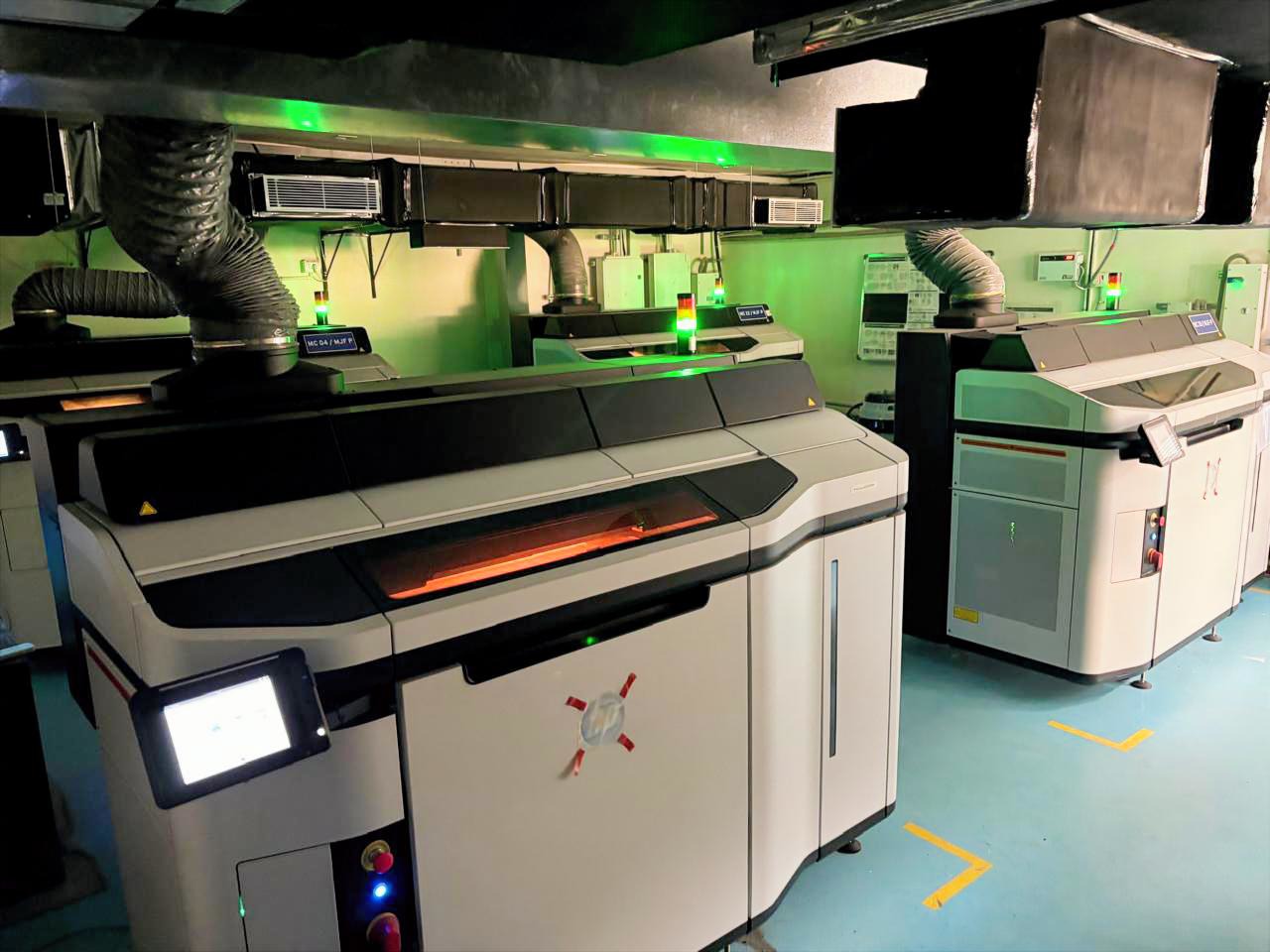
A lattice design is only as good as the process that prints it. We run HP MJF 3D printing in Nylon PA12 and PA12 CF, and every lattice job gets checked against real MJF tolerances before it goes anywhere near a printer, not generic engineering assumptions. If you're working on a topology-optimized or lattice-based redesign, get an instant quote and see what it really costs to print.
Frequently Asked Questions
1. What is a 3D printed lattice structure?
It's an internal cell structure, a repeating network of struts and nodes, that replaces solid material inside a printed part. Using lattice structures reduces weight and material use while keeping mechanical performance intact, because the load spreads across many small members instead of one solid mass. This is the core idea behind lattice structures in 3D printing generally, whether the interior lattice doubles as a support structure for an overhang or makes up the part's entire internal structure.
2. How much weight can a lattice structure actually save?
It depends on the part and load case, so there's no single universal number. HP's own documented redesign of an aluminum bracket into an MJF part with topology optimization and a lattice interior achieved a 90% weight reduction, going from 355 grams to 23 grams.
3. What's the difference between a gyroid and a honeycomb structure of a lattice?
A gyroid is a continuous curved surface with no flat sections, and it spreads load evenly in every direction, which is why it shows up in heat exchangers and medical implants. A honeycomb is a 2D hexagonal pattern extruded into columns, and it resists crushing forces best in one primary direction, which suits sandwich panels and other types of lattice structures built for one-way loading.
4. Can any 3D printer produce a lattice structure?
Not equally well. Processes that don't need internal supports inside the part, like HP MJF, are much better suited to print structures with complex internal geometry than methods that print supports inside cavities, since trapped material is difficult or impossible to remove once the part is sealed.
5. Does designing a lattice structure need special software?
Yes, generally. Standard CAD tools aren't built for generating and latticing thousands of repeating cells. Topology optimization and lattice-generation design software, including tools like Materialise Magics or Autodesk Netfabb, handle that part of the job, and the resulting design still needs to be checked against the printing process's real tolerances before it's sent to print.

.png)